
The brewing system utilizes two different solenoid valves. Both valves are "normally closed", meaning the valve is closed in the de-energized state.
| Actuation | Pilot Operated |
| Functional Type | Two-Way |
| Flow Pattern | Normally Closed |
| Body Material | Brass |
| Threading/Process Connection | N.P.T. |
| Pipe Size (N.P.T.) | 1/2" |
| Orifice Size | 5/8" |
| Seal/Elastomers | Buna N |
| Coil Construction and Type | ½" NPT Conduit |
| Voltage | 110/50 - 120/60 |
A Dayton valve is used to control the flow of water into the sparge vessel. A second Dayton valve is used to control the flow of water through the wort chiller.

The Dayton valve is a pilot-operated valve, meaning the valve requires differential pressure in order to open. Finding a good pilot-operated solenoid valve is pretty straightforward. A plastic valve could be used for this application to save money. Temperature is not a concern.
| Series | 7 | 7000 |
| Actuation | 1 | Direct Operated |
| Functional Type | 2 | Two-Way |
| Flow Pattern | 1 | Normally Closed |
| Family | 5 | n/a |
| Body Material | S | 430F stainless steel |
| Threading/Process Connection | N | N.P.T. |
| Pipe Size (N.P.T.) | 3 | 3/8" |
| Orifice Size | 3 | 3/8" |
| Seal/Elastomers | N | Buna N |
| Mechanical Options | OO | None |
| Enclosure Type | NO | Nut and Washer |
| Coil Construction and Type | C1 | ½" NPT Conduit, 10 Watt |
| Terminations and Option Codes | 11 | Class F Coils with 18" Leads |
| Voltage | P3 | 110/50 - 120/60 |
A Honeywell valve is used to control the flow of wort between the mash vessel and the boil vessel. A second Honeywell valve is used to control the flow of wort between the boil vessel and the wort chiller.
I probably spent more time trying to find an affordable stainless steel 3/8" (1/2" preferred) direct-lift solenoid valve than any other component within the brewing system. And I'm not crazy with my final selection. These valves tend to have smaller ports, even smaller orifices and low flow rates.
The Honeywell valve actually works quite well in between the mash vessel and the boil vessel. I use 3/8" stainless steel tubing and can easily achieve a flow rate of nine gallons per 45 minutes, or 12 G.P.H.
The Honeywell valve in between the boil vessel and the wort chiller
originally gave me fits. The orifice would become plugged with
hops and hot break. Honeywell doesn't recommend the use of the
7121 with liquid having suspended solids (i.e. wort). I eventually
fitted the inside of the boil vessel bottom drain with a rolled
brass screen. This solved the problem, but I'd still prefer to
have larger ports and orifices.
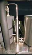
I prototyped most of the plumbing using soldered ½" copper pipe. I took the prototype pieces to a professional pipe bender to have the stainless steel tubing bent. I probably only had 10 pieces, but the pipe bender charged a minimum of $90 just to setup the equipment. He did a great job. I can't imagine trying to bend the stainless steel tubing at home.
All of the stainless steel tubing is couple using Swagelock® stainless steel compression fittings. I spent more money on stainless steel fittings than any other aspect of the brewing system. But the Swagelock® compression fittings are invaluable. They allow me to easily tear down the system for cleaning.
The mash vessel recirculating path is probably too complex involving too many corners. This tends to slow the overall recirculation rate. One aspect of the plumbing design that really caused problems was the plumbing leading to the sparge/recirculating ring. Both the dough-in/sparge water and wort recirculation path enter the mash vessel at the same point. The resistance within the recirculating ring tends to back the wort up into the sparge vessel. I formed a trap in the sparge water line leading to the mash vessel, but apparently, it wasn't adequate. I need to consider some form of back flow preventer here or another solenoid valve.
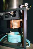
You can see that all of the plumbing in the mash recirculation path (the RIMS tube and mash vessel insulation was removed for the picture) and the mash vessel are insulated. The mash vessel is wrapped in a camping mat with holes cut to accept the pot handles, drains and thermowell fitting. You can see the outlet cover with four LED indicators,
A similar outlet cover with four LED indicators is located to the left of the boil vessel,
All of the electrical wiring is contained within conduit. Both of the electric heater elements plug into weatherproof electrical boxes.
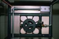
Both of the propane stoves are plumbed to a single propane tank using 3/8" galvanized pipe. I used a bell reducer to couple the stove valve to the pipe. My local Orchard Supply hardware store threaded the ends of the longer sections of pipe. I used a union to join the long section of pipe running in between the two propane stoves. I used teflon paste to seal the threads and tested the seals using water with a small amount of dish soap.
When I first prototyped the brewing system, I used a series of ball valves to allow a single pump to transfer dough-in and sparge water from the sparge vessel to the mash vessel, to recirculate wort to the mash vessel and to drain wort to the boil vessel. Since my ultimate goal was to fully automate the brewing system, I needed to replace the ball valves with solenoid valves. Stainless steel solenoid valves are so expensive that I found out that it was cheaper to eliminate some of the valves and introduce a second pump and bottom drain. The pump actually serves as somewhat of a valve. And the second bottom drain eliminates the need for the valve that would have switched between the mash vessel and the boil vessel.
All of the ½" bottom drains have a ½" N.P.T. female-to-male elbow. This reduces the width and depth of the brewing rack. A right-angle bottom drain could have been welded to the pot, but this would have made the pot far less versatile in the event the orientation were to change.
I have ½" stainless steel ball valves attached to all of the ½" bottom drains. The ½" (3/8") O.D. stainless steel tubing is coupled to the ½" stainless steel ball valve using a ½" (3/8") Swagelock® stainless steel compression fitting. This allows me to remove the vessels for cleaning without dripping water/wort all over the place. The sparge ball valve and the mash recirculating ball valve are normally open. The mash ball valve leading to the boil vessel is partially closed to control the sparge flow rate. The boil ball valve could be partially closed to adjust the flow rate of wort though the chiller, however, I normally run with the valve wide open.