
Wicked Beernut Home - Halloween Home
The Grave Jumper
Most of the pictures on this web page are thumbnails. Each thumbnail is ¼ size and ¼ quality of the full image, approximately 3K - 10K bytes. Each thumbnail is a hyperlink to a full image that is approximately 30K - 100K bytes.

Introduction
Doug Ferguson describes the concept of a Grave Jumper at Phantasmechanics.
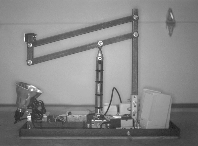
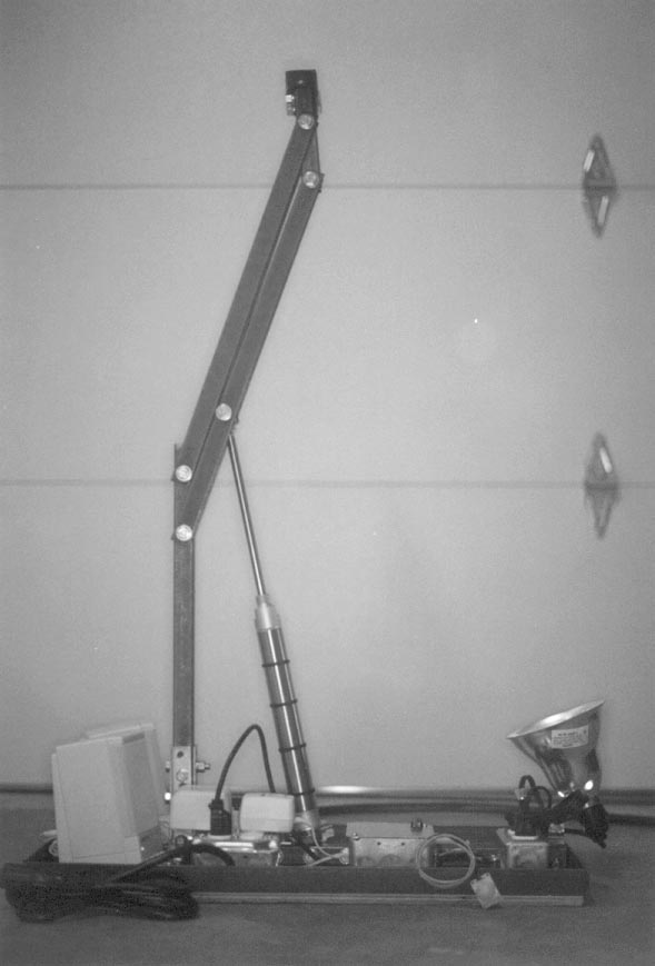
My Grave Jumper is based on a four-bar linkage. Refer to my Haunt Mechanics page for a description of a four-bar linkage.

My design was based on Brent Ross' Pneumatic Lifter at Devious Concoctions. Brent made the ground and coupler bars from 1 1/2" angle iron and the crank and follower bars from single bars of 1/8" flat steel.
Edwin includes an example of a four-bar linkage that he used in conjunction with a Trash Can Trauma. Edwin made the ground and coupler bars from 1/2" square steel tubing and the crank and follower bars from double bars of flat steel.
I combined the two designs, using Brent's dimensions with 1" square steel tubing and double bars of 3/16" flat steel.
The tombstone is made using Dow blue insulating foam board and a half profile foam prop skull (#SK1135, $5.99) from Steve Hickman's Terror Syndicate GraveStalkers.
The head and torso are constructed using on a Terror Syndicate Monster Mud prop frame. Steve features Monster Mud props in his Home Haunter's Handbooks.
The rigid urethane foam prop hands ($19.99) are from Steve Hickman's Terror Syndicate GraveStalkers.
Lifter
 -
-
|
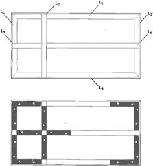
(2) 13" - 1 1/4" Angle Iron |
L2 + L4 |
|
(2) 26" - 1 1/4" Angle Iron |
L1 + L3 |
|
|
|
|
(1) 12 3/4" x 25 3/4" - 1/2" Plywood |
|
|
|
|
|
(1) 1" - 1" Square Tubing |
L15 |
|
(1) 18 1/2" - 1" Square Tubing |
L6 |
|
(1) 5 3/4" - 1" Square Tubing |
L5 |
|
(1) 12 1/2" - 1" Square Tubing |
L7 |
|
(1) 5 1/4" - 1" Square Tubing |
L12 (Coupler) |
|
(1) 20" - 1" Square Tubing |
L14 (Ground) |
|
|
|
|
(2) 4 1/2" - 1" x 3/16" Flat Bar |
L16 + L17 |
|
(4) 20" - 1" x 3/16" Flat Bar |
L10 + L11 (Crank) and L8 + L9 (Follower) |
|
|
|
|
(1) 6" - 1 1/2" Angle Iron |
L13 |
|
|
|
|
(4) 1" x 5" Angle Brackets |
|
|
(4) Corner Brackets |
|
|
|
|
|
Mannesmann-Rexroth 8" Air Cylinder, M-12DXP-80, Motion Industries, Inc. |
$46.10 |
|
SMC Corporation Sub-plate, SPF0191-02, Motion Industries, Inc. |
$16.75 |
|
SMC Corporation Valve Body and Solenoid (1), NVFS2100-3FZ, Motion Industries, Inc. |
$54.30 |
|
Mannesmann-Rexroth Flow Control Valves (2), 540-632-600-1, Motion Industries, Inc. |
$12.80 x 2 = $25.60 |
|
Mannesmann-Rexroth Foot Bracket, ML073790048, Motion Industries, Inc. |
$2.95 |
|
|
|
|
K76 PIR Movement Detector Module, http://www.web-tronics.com/ |
$11.95 |
|
Radio Shack, 20-Second Recording Module, 276-1323, http://www.radioshack.com |
$9.99 |
|
First Step Microcontroller Kit (unassembled), #3-475, http://www.robotstore.com |
$32.00 |
|
Crydom Solid State 5A SIP DC, CX240D5, CC1063-ND, http://www.digikey.com |
$9.02 x 2 = $18.04 |
|
Momentary SPST Switch, #275-618, http://www.radioshack.com |
$1.89 |
|
Green Blinking LED, #276-305, http://www.radioshack.com |
$1.69 |
|
LED Holder, #276-079, http://www.radioshack.com |
$0.59 |
|
Mini Project Enclosure (2.125" x 1.375" x 0.580"), http://www.radioshack.com |
$1.99 |
|
Dual Mini Grid-Style PC Board, #276-148, http://www.radioshack.com |
$1.49 |
|
5 1/2" Clamp Light, Orchard Supply Hardware |
$7.99 |
|
Metal Standoffs (10), #276-195, http://www.radioshack.com |
$1.29 - Set of Four |
|
3' 3-Conductor Intercom Wire, #278-871, http://www.radioshack.com |
$4.99 - 50' |
|
Four-Pin Male Connector and Four-Pin Female Connector, #274-224 and #274-234, http://www.radioshack.com |
$1.19 + $1.19 |
|
1 /8" Phono Plug Jack, http://www.radioshack.com |
|
|
Heavy Duty 9 V Battery Snap Connectors, #270-324, http://www.radioshack.com |
$1.89 - Package of Five |
|
300 mA 9 V Transformer, #273-1767, http://www.radioshack.com |
$8.99 |
|
Amplified Speakers |
|
|
4" x 2 1/8" Handy Box (Single Outlet), Duplex Cover and White Duplex Receptacle, Orchard Supply Hardware |
$0.59 + $0.39 + $0.49 = $1.47 |
|
4" Square Outlet Box (Dual Outlet), Cover and White Duplex Receptacles (Two), Orchard Supply Hardware |
$1.39 + $0.89 + 2 x $0.49 = $3.26 |
|
4" Square Outlet Box (Dual Outlet) and Cover, Orchard Supply Hardware |
$1.39 + $0.39 = $1.78 |
|
6' Household Extension Cord |
$1.49 |
|
Two 3-Wire Electrical Cords with Grounded Plugs |
|
|
3 /8" Romex NM Connector (4), Orchard Supply Hardware |
$0.99 - 4 Connectors |
|
1 /4" NPT x 1/4" Compression Fittings (2), Motion Industries, Inc. |
$2.18 x 2 = $4.36 |
|
Teflon Thread Seal Tape |
$1.19 |
|
1 /4" NPT Female Plug Air Quick-Disconnect Fitting |
|
|
1 /4" Brass Nipple |
$1.09 |
|
1 /4" Brass Couple |
$1.79 |
|
Flat Black Spray Paint |
|
|
2' of 1/4" Polyethylene Tubing |
$0.07 per foot |
|
|
|
|
6 - 3/8" Locknuts |
|
|
35 - 3/8" Nuts |
|
|
35 - 3/8" Lockwashers |
|
|
41 - 3/8" Washers |
|
|
2 - 1 1/2" long 3/8" Bolts |
|
|
1 - 2 1/2" long 3/8" Bolt |
|
|
22 - 2" long 3/8" Bolts |
|
|
16 - 1" long 3/8" Bolts |
|
|
|
|
|
10 - 1/2" Wood screws |
|
|
2 - 3" Wood screws |
|
|
2 Bolts, Washers, Lockwashers and Nuts (to secure solenoid valve to 1/2" playwood) |
|
|
|
|
|
2 15" American Camper Steel Tent Stakes |
|
Mechanical
The ends of the 1 1/4" angle iron, L1, L2, L3 and L4, are cut at 45° angles. Position L1, L2, L3 and L4 to form a frame. Position the four 1" corner brackets such that the frame is square. Mark the four holes (depicted in the illustration) of each corner bracket on the angle iron frame. Drill 3/8" holes in the angle iron corresponding to the marks. Drill out the four holes in each corner bracket using a 3/8" drill bit.
Reposition L1, L2, L3 and L4 on the 1/2" plywood. Mark the holes in the angle iron frame on the 1/2" plywood. Drill a 1/8" pilot hole through the 1/2" plywood in the center of each mark. From the underside of the 1/2" plywood (using the pilot holes as a guide), countersink each 3/8" bolt and washer using a 1" spade bit. Drill out the pilot hole using a 3/8" drill bit.
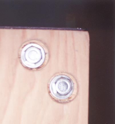
This picture shows how the 3/8" bolts and washers are countersunk into the bottom of the 1/2" plywood using a 1" spade bit.
Reposition the 1 1/4" angle iron frame and corner brackets on the 1/2" plywood. Secure the frame and brackets to the 1/2" plywood using 1" long 3/8" bolts, washers, lockwashers and nuts. A 3/8" bolt with washer is inserted from the underside of the 1/2" plywood. Just hand-tighten the nuts for now.
Note: This incremental approach of assembling, marking, disassembling, drilling, reassembling, ..., will require that you repeatedly assemble and disassemble the platform. This is the approach that I took in building the platform and developing these instructions. In theory, you should be able to mark and drill all of the holes in all of the iron members at the same time and assemble the platform once.
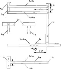
Drill a 3/8" hole 1/2" from the end of L5 and L6. Note that these holes are drilled from the "top" through to the "bottom" of L5 and L6. Drill a pair of 3/8" holes 3 1/2" apart, centered 5 3/4" from the opposite end of L6 (refer to the illustration). Note that these holes are drilled through the "sides" of L6. Drill a 3/8" hole 1/2" from each end of L7. Position L5, L6 and L7 as shown in the illustration. Mark the holes in the 1" square tubing on the 1 1/4" angle iron frame. Disassemble the platform and drill 3/8" holes in the angle iron corresponding to the marks.
Reposition L1, L2, L3 and L4 on the 1/2" plywood. Mark the holes in the angle iron frame on the 1/2" plywood. Repeat the process of drilling pilot holes and countersinking the 3/8" bolts and washers. Reposition the angle iron frame, corner brackets and square tubing on the 1/2" plywood. Secure the 1" square tubing to the 1/2" plywood and 1 1/4" angle iron frame using 2" long 3/8" bolts, washers, lockwashers and nuts. Just hand-tighten the nuts for now.
Position L14 at the point where L5, L6 and L7 meet. Position the four 1" x 5" angle brackets between L5, L6, L7 and L14. Mark the two holes (depicted in the illustration) of each angle bracket on the 1" square tubing. Disassemble the platform and drill 3/8" holes in the 1" square tubing corresponding to the marks. Drill out the two holes in each angle bracket using a 3/8" drill bit.
Reposition L5, L6 and L7 on the 1/2" plywood and 1 1/4" angle iron frame. Mark the holes in the 1" square tubing on the 1/2" plywood. Repeat the process of drilling pilot holes and countersinking the 3/8" bolts and washers. Secure the 1" square tubing to the 1/2" plywood and 1 1/4" angle iron frame using 2" long 3/8" bolts, washers, lockwashers and nuts. Just hand-tighten the nuts for now.
The original holes in the angle brackets can't be used to secure L14 since the holes are slightly offset. A hole that is offset to the right on one bracket will be offset to the left on the opposite bracket and the holes won't line up. New holes need to be drilled in the upright members of the angle brackets. The holes should be drilled on center. Holes in opposite angle brackets should be drilled in the same location. Holes in adjacent angle brackets should be offset by 1/2". Secure the 1" square tubing and brackets using 2" long 3/8" bolts, washers, lockwashers and nuts.
Drill a 3/8" hole 1 1/2" and 4 1/2" from the end of L14 opposite the angle brackets. Drill a 3/8" hole 1/2" from each end of L8, L9, L10 and L11. Drill a 3/8" hole 6 3/4" from one end of L10 and L11.
Drill a 3/8" hole 1/2" and 3 1/2" from one end (the bottom) of L12. These holes will be used to secure L8, L9, L10 and L11 to L12. From the opposite end (the top) of L12, on the adjacent sides, drill a pair of 3/8" holes 1/4" and 7/8" from the end respectively. These holes will be used to secure L13 to L12.
Drill a pair of 3/8" holes 3" apart centered on L13. Position the top of L12 against the adjacent side of L13. Mark the holes in L12 on L13. Drill 3/8" holes in the 1 1/2" angle iron corresponding to the marks.
Drill a 3/8" hole through the center (from the left side through to the right side) of L15. Drill a hole on the adjacent side of L15 (the bottom) to accept the threaded end of the air cylinder shaft.
Drill a 3/8" hole 1/2" from each end of L16 and L17. Drill a 3/8" hole in the center of L16 and L17. This holes is denoted by F1 in the illustration.
L8, L9, L10 and L11 are attached to L12 and L14 using 2" long 3/8" bolts, two washers and a locknut.
L13 is attached to L12 using a pair of 1 1/2" long 3/8" bolts, lockwashers and nuts.
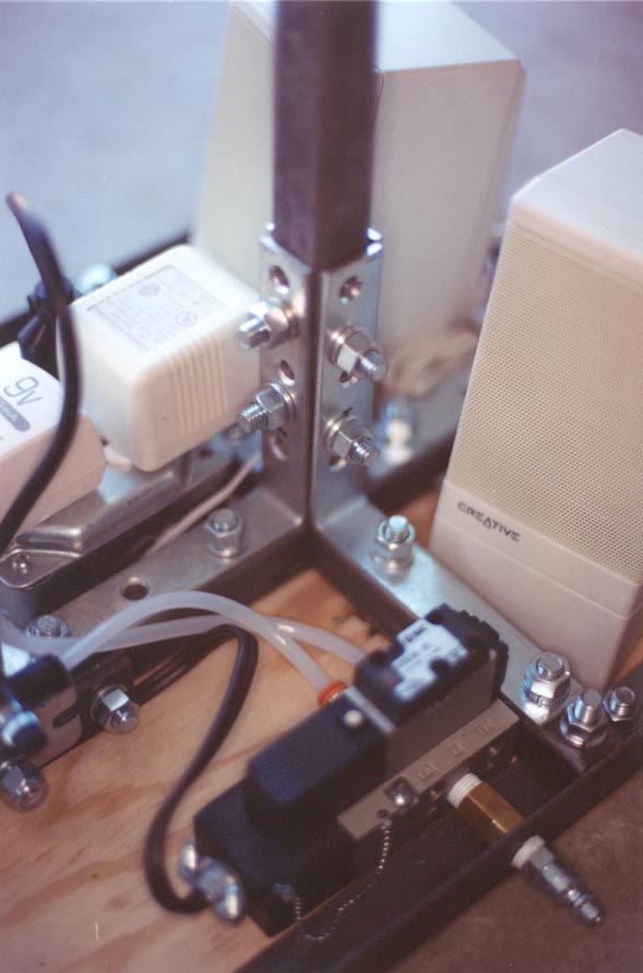
L16 and L17 are sandwiched together and attached to L6 using a pair of 2" long 3/8" bolts, washers, lockwashers and nuts. L16 and L17 serve to center the air cylinder under L15.
Drill a 3/8" hole in the foot bracket, adjacent to the large hole that accepts the air cylinder. The 3/8" hole should be on center and 1/2" from the edge of the foot bracket. The foot bracket is attached to the air cylinder using a large washer, lockwasher and the supplied nut. The foot bracket is attached to L6, L16 and L17 using a 2 1/2" long 3/8" bolt, two washers and a locknut.
Secure L15 to the shaft of the air cylinder using a lockwasher and a pair of jam nuts. Secure L15 to L10 and L11 using a using a 2" long 3/8" bolt, two washers and a locknut.
Electrical
Warning: 110 volts can be extremely dangerous. Props involving 110 volts can cause serious injury or even death.
A three-wire electrical cord with a grounded plug is wired through a 3/8" Romex NM connector to a pair of white duplex receptacles in a 4" square outlet box. The outlet box is positioned in the corner of L6 and L7 and secured to the 1/2" plywood using a pair of 1/2" wood screws.
The solid-state relays are soldered to a mini grid-style PC board. The stamp, digital voice recorder and PC board are secured to the bottom of the other 4" square outlet box using metal standoffs.
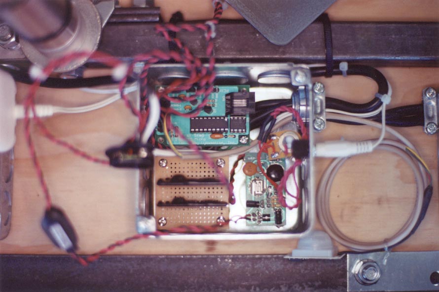
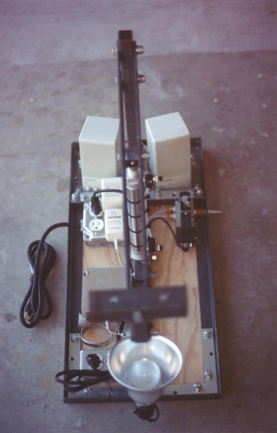
This picture shows the 4" square outlet box with the cover removed. You can see the stamp, digital voice recorder and solid-state relays mounted inside. You can see the two nine volt battery snap connectors. The snap connectors are wired to the nine volt transformer and supply power to the stamp and the digital voice recorder.
A three-wire electrical cord with a grounded plug is wired through a 3/8" Romex NM connector to the solid-state relays in the outlet box. The tab connecting the two sockets of the white duplex receptacle in the 4" x 2 1/8" handy box is removed and the solid-state relays are individually and independently wired to the two sockets.
The 4" x 2 1/8" handy box is positioned in the corner of L2 and L6 and secured to the 1/2" plywood using a pair of 1/2" wood screws. The 4" square outlet box is centered between the other 4" square outlet box and the 4" x 2 1/8" handy box and secured to the 1/2" plywood using a pair of 1/2" wood screws.
The socket is cut from the 6' household extension cord using wire cutters. The extension cord is wired through a 3/8" Romex NM connector to the solenoid valve.
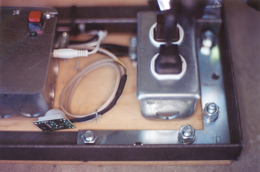
This picture shows the 4" square outlet box on the left that contains the stamp, digital voice recorder and solid-state relays. On the cover of the 4" square junction box, you can see the momentary power-on-reset switch and the flashing green LED "ready" indicator. You can see the 1/8" phono plug from the amplified speakers that is plugged into a 1/8" phono jack in the side of the outlet box. You can see the three-conductor intercom wire connected to the K76 PIR movement detector. A pair of electrical wires corresponding to each of the solid-state relays runs from the 4" square outlet box to the receptacles of the 4" x 2 1/8" handy box. The clamp light and the solenoid valve are plugged into the 4" x 2 1/8" handy box.
Pneumatic
Warning: Compressed air can be extremely dangerous. Props actuated by pneumatic cylinders can cause serious injury or even death.
The flow control valves are wrapped with Teflon tape and threaded into the air cylinder. The 1/4" NPT x 1/4" compression fittings are wrapped with Teflon tape and threaded into the output ports of the solenoid valve.
The 1/4" brass nipple is wrapped with Teflon tape and threaded into the solenoid valve. The solenoid is positioned in the corner of L1 and L7. A hole is drilled in L1 to accept the 1/4" NPT female quick-disconnect fitting. The 1/4" NPT female quick-disconnect fitting is wrapped with Teflon tape and joined with the 1/4" brass nipple using a 1/4" brass couple through L1. The solenoid valve is secured to the 1/2" plywood using a pair of bolts, washers, lockwashers and nuts.
The 1/4" NPT x 1/4" compression fittings in the solenoid valve are plumbed to the flow control valves in the air cylinder using 1/4" polyethylene tubing.
 -
- -
-
Head and Torso
The construction of the head and torso are based on a Terror Syndicate Monster Mud prop frame. For details on the construction of a Monster Mud prop frame refer to Steve Hickman's Terror Syndicate Home Haunter's Handbooks.
|
(1) 8" x 16" 1/2" Plywood (Shoulder Plate) |
|
(1) 2x4-20" (Shoulders) |
|
(2) 2x3-13 1/2" (Upper Arms) |
|
(2) 2x3-8 1/2" (Lower Arms) |
|
1" Chicken Wire |
|
Drywall Screws |
|
1" Wood Dowel |
|
Foam Wighead |
|
XR-1592 Two-Part Expanding Urethane Foam |
|
Old Shirt |
|
Latex Mask |
Steve advocates inserting a plastic grocery bag into the latex mask and filling it with foam insulation from a spray can. I've found that it's much easier to insert a foam wighead into the plastic grocery bag and pour a two-part expanding urethane foam in between the grocery bag and the wighead. The two-part expanding urethane foam sets up in minutes.
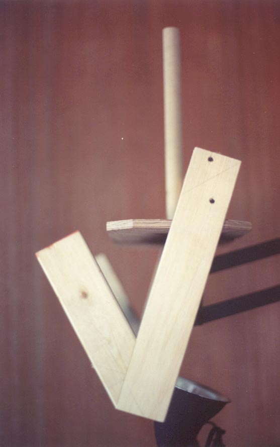
A pair of 3" wood screws is used to secure the prop frame to the 6" - 1 1/2" angle iron (L13).
 -
-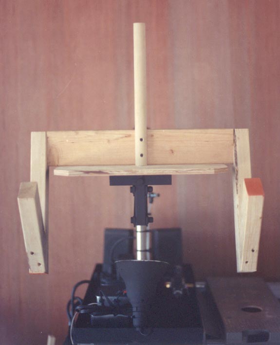
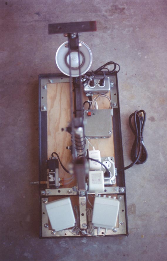
I covered the prop frame with chicken wire, but rather than apply Monster Mud to the chicken wire I opted to simply dress the torso in a plaid shirt in order to minimize the weight.
The momentum of the head and torso tend to lift the front of the Grave Jumper platform off the ground. I used a pair of 15" American Camper steel tent stakes to hold the front of the Grave Jumper platform to the ground. The hook on the top of the tent stake slips over the 1 1/4" angle iron frame of the Grave Jumper platform.
Software
The Grave Jumper is controlled by a First Step stamp microcontroller. Here is the stamp PBASIC program that controls the Grave Jumper,
Refer to the Beginner's Guide to Haunting with a Stamp Microcontroller for more information on how the First Step stamp microcontroller is used to control the Grave Jumper and haunt props in general.