
Wicked Beernut Home - Halloween Home
Most of the pictures on this web page are thumbnails. Each thumbnail is 1/4 size and 1/4 quality of the full image, approximately 3K - 10K bytes. Each thumbnail is a hyperlink to a full image that is approximately 30K - 100K bytes.
 -
-
 -
- -
-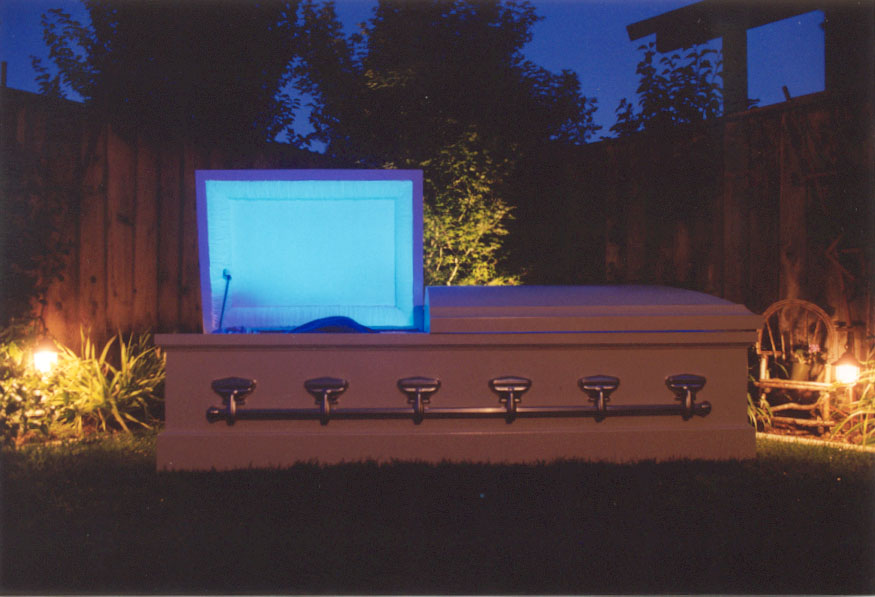
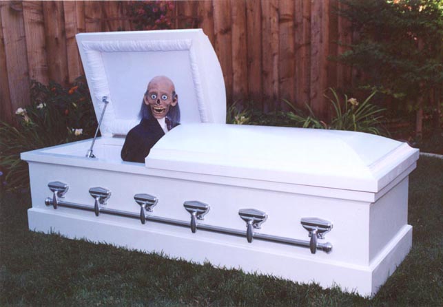
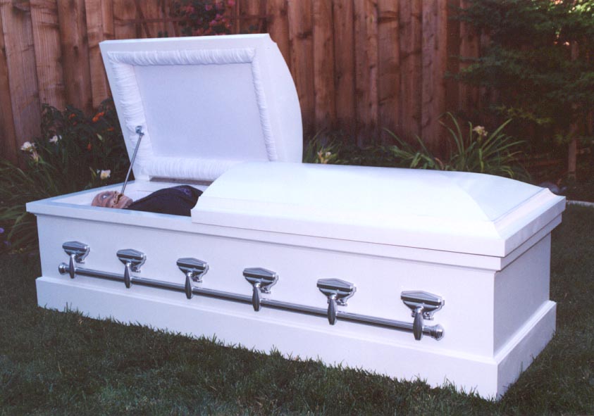
My coffin, although completely different in style and considerably different in construction, was inspired by Scott Nicholson's coffin featured at The Yard and equally inspired by Brent Ross' interpretation of Scott's coffin at Devious Concoctions.
Brent recommended the coffin hardware (arms, tips, bars, ...) which I used. I opted to order 5' 6" bars as opposed to the shorter length which Scott and Brent used. The shorter length is better suited for Scott's toe-pincher style coffin.
Brent recommended the pneumatic cylinder (with flow control valves and fittings) and the solenoid valve which I used to open and close the lid. I purchased a second pneumatic cylinder and solenoid valve that I used to raise and lower the corpse.
More importantly, Brent provided me with excellent advice throughout this entire project. I owe Brent a great deal of thanks.
I also want to thank Denny Dahm at Terror By Design. Denny provided me with his "Haunt Technology Made Simple" Seminar Outline which detailed the use of a Stamp microcontroller to: animate a skull (with servomotors); actuate a pneumatic cylinder using a solenoid valve via a solid-state relay; and trigger a Radio Shack recording module. Denny is a true professional and this is reflected in the quality of his products.
I spent an average of approximately six hours a week for five months to complete this project. That works out to three person-weeks (one person, 40 hours a week for three weeks). I'm still trying to dig up old receipts, but I'm sure that I spent well over $2,000 on this project. I'm sure that I could have purchased a brand new, "real" coffin for far less. I'm not sure that I'd encourage anyone to build this entire project as it's specified here. I'm hoping that you will browse through this webpage and find ideas that you can apply to your projects.
|
Description |
Unit |
Approximate |
|
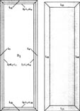
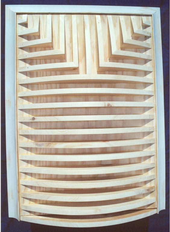
L1, L2 = 8' L3, L4 = 2' 6" |
L1, L2 = 6' 6" L3, L4 = 2' |
|
L5, L6, L7, L8 = 8' L9, L10, L11, L12 = 2' 6" |
L5, L6 = 6' 6" L7, L8 = 6' 7 1/2" L9, L10 = 2' L11, L12 = 2' 1 1/2" |
|
L13, L14 = 8' (1 1/2" x 2 3/4") L15, L16, L17, L18 = 4' (1 1/2" x 1 3/4") L19, L20, L21, L22 = 2' 6" (1 1/2" x 1 3/4") L23, L24 = 2' 6" (1 1/2" x 2 3/4") |
L13, L14 = 6' 8" L15, L16 = 3' L17, L18 = 3' 9" L19, L20, L21, L22 = 2' 3" L23, L24 = 2' 2" |
|
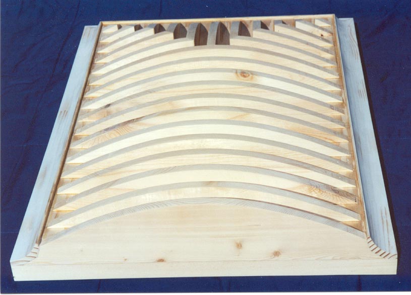
M1, M2, M3, M4 = 4' M5, M6 = 2' 6" |
M1, M2 = 3' M3, M4 = 3' 9" M5, M6 = 2' 3" |
|
M7, M8 = 8' M9, M10 = 2' 6" |
M7, M8 = 6' 7 1/2" M9, M10 = 2' 1 1/2" |
|
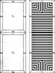
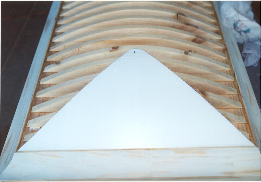
P = 4' x 8' |
P1 = 2' x 6' 6" |
|
P2, P3 = 2' x 4' |
|
|
L25, L26, L27, L28 = 8' L29 , L30 = 2' 6" |
|
|
P4, P5 = 2' x 4' P6, P7 = 2' x 4' |
P4, P5 = 2' x 3' P6, P7 = 2' x 3' 6" |
|
H = 2' x 4' |
|
|
$22.49 |
|
|
$3.99 x 6 = $23.94 |
|
|
$3.99 x 6 = $23.94 |
|
|
Coffin Hardware, Abaco Platers, Philadelphia, PA, (215) 634-6983, Contact: Jerry Sr. |
$93.20 - Part Number: #19 (273-81), Detailed Part Info: 270 arm, 381 tip and a 1.25 oval bar |
|
|
$3.99 x 2 = $7.98 |
|
|
$3.99 x 2 = $7.98 |
|
|
$4.99 - 20" x 30" |
|
Tools: Table Saw, Compound Miter Saw, Biscuit Joiner, Pneumatic Brad Nailer, Router with Roman Ogee Bit and 3-Wing Laminate Trim Bit, Palm Sander, Jigsaw, Drill, 36" Bar Clamps (8), 6" Bar Clamps (6), Hammer, Nail Set, ...
Miscellaneous: #10 and #20 Biscuits, Assorted Brads, 1" #8 Wood Screws, 1 1/4" #10 Wood Screws, Wood Patch, Exact-o Knife, Framing Square, Wood Glue, Sandpaper, ...
Note 1
: I am an amateur woodworker. I have never taken a woodworking class. I have never even read a woodworking book or magazine. I don't want to imply that the techniques described here are good woodworking practices. I take a rather common sense approach to most of my projects. There are most likely better techniques than what I've employed.Note 2
: I am an amateur woodworker with very expensive tools. And while this project could have been completed with far less, these tools simplified the project and likely enhanced the finished product.
 -
- 
Warning: Compressed air can be extremely dangerous. Props actuated by pneumatic cylinders can cause serious injury or even death.
|
$53.70 |
|
$16.75 |
|
$54.30 |
|
$12.80 x 2 = $25.60 |
|
$2.95 |
|
$2.79 |
|
$0.59 |
|
$0.39 |
Tools: Drill, Socket Wrench
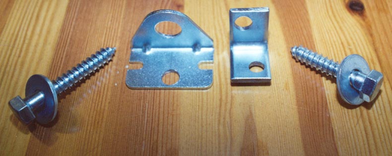
This is the hardware used to attach the 12" Pneumatic Cylinder to the wall of the coffin and the lid frame (from left to right),
Note
: The 3 1/2" long, 1/2" Lag Screw is ultimately used with the Angle Bracket and the 2" long, 1/2" Lag Screw is used with the Mannesmann-Rexroth Foot Bracket.The large hole in the Mannesmann-Rexroth Foot Bracket accepts the Pneumatic Cylinder. I added the smaller hole to accept a 1/2" lag screw. The Pneumatic Cylinder "pivots" on this lag screw at the lid opens.
The bracket on the right is cut from a 1 1/8" angle bracket. The original hole was drilled out to accept the Pneumatic Cylinder. I added a second hole to accept a 1/2" lag screw.
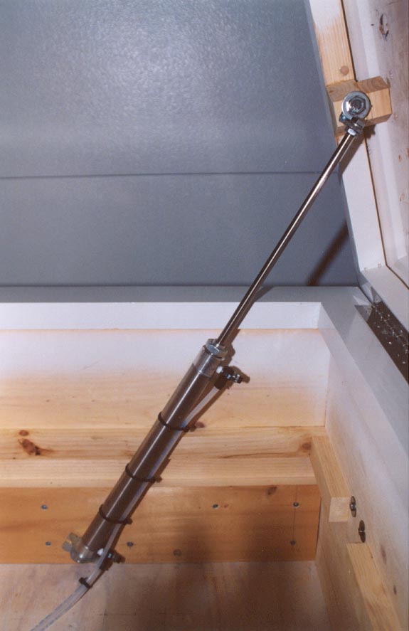
The wall of the coffin is 3/4" thick. The base molding is 3/4" thick. And I reinforced the inside wall of the coffin with 6" x 22 1/2" board of 3/4" pine. That's 2 1/2" of pine. I drilled a 3/8" hole through the reinforcing board, through the wall of the coffin and into the base molding and secured the Pneumatic Cylinder to the coffin using a 2" long, 1/2" lag screw.
The lid frame is 1 5/8" wide. I glued a 1 3/4" wide trapezoidal block of pine to the lid frame. I glued a second, matching trapezoidal block of pine between the first block and the plywood base of the lid. The first trapezoidal block ensures that the pneumatic cylinder is parallel to the wall of the coffin. The second trapezoidal block helps to distribute the force of the Pneumatic Cylinder to the rest of the lid. I drilled a 3/8" hole through the first wood block into the lid frame and secured the pneumatic cylinder to the coffin lid using a 3" long, 1/2" lag screw.
From this picture, you can see the two black flow control valves which are threaded at the top and bottom of the pneumatic cylinder.
Warning: 110 volts can be extremely dangerous. Props involving 110 volts can cause serious injury or even death.
|
$9.99 |
|
$40.00 |
|
$9.02 x 2 = $18.04 |
|
|
|
|
|
|
|
$1.29 - Set of Four |
|
|
|
$0.59 + $0.39 + $0.49 = $1.47 |
|
$1.39 + $0.89 + 2 x $0.49 = $3.26 |
|
$3.99 |
|
$1.49 x 3 = $4.47 |
|
$0.99 - 4 Connectors |
Tools: Soldering Iron, Screwdriver, Drill
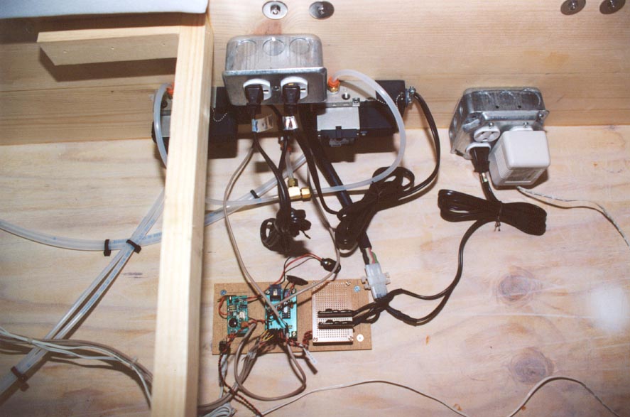
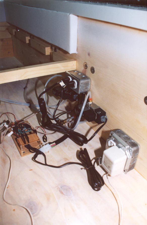
Along the back wall of the coffin (from left to right),
Below the Two-Outlet Junction Box and between the Lid and Corpse Solenoid Valves (from left to right),
On the 7 1/2" x 3 1/2" piece of 1/8" hardboard (from left to right),
The Microcontroller and Circuit Board have mounting holes and were each suspended using four metal standoffs. The Recording Module didn't have mounting holes and it didn't have real-estate to drill mounting holes. I epoxied a pair of metal standoffs in opposite corners of the Recording Module.
The Four-Outlet Junction Box provides 110 volts to the coffin. The DC transformer provides power to the amplified speaker. The brown electrical cord provides power to both of the Crydom solid-state relays.
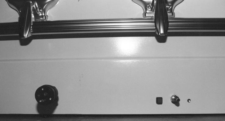
On the back of the coffin (from left to right),
If there is interest, I will revise this website to discuss how the Software was written.
|
White Crepe Fabric |
|
Foam Core |
|
1 /8" Hardboard |
|
3 /8" Plywood |
|
Spray Adhesive |
|
Aleene's Original Tacky Glue |
|
1" Foam |
|
4" Foam |
|
Flat-White Spray Paint |
Tools: Jigsaw, Table Saw, Staple Gun, Stapler, Exact-o Knife, Scissors
Miscellaneous: Needle and White Thread
If there is interest, I will revise this website to discuss how the Bed and Lining were constructed.
This picture shows the supports for the bed. The bed supports are made from 1 1/2" x 1" blocks of pine. The "gaps" between the bed supports correspond to the nuts and bolts that secure the coffin bars to the sides of the coffin. The top of the bed support corresponds to the top of the corpse assembly and the corpse assembly just happens to correspond to the height of the nuts and bolts. The height of the bed support is 9 1/2".
 -
-
|
$27.00 |
|
Bucky's Right Arm and Hand, CH-46R/D, http://www.boneyardbargains.com |
$9.50 |
|
Bucky's Left Arm and Hand, CH-46L/D, http://www.boneyardbargains.com |
$9.50 |
|
2 x 4 #2 Common Pine |
L1 = 15 5/8" L2 = 8" L3 = 9" L4 = 6 1/2" |
|
19 1/2" Length of Unistrut, Home Depot |
|
|
U-Bolts (2), Home Depot |
|
|
1 /2" x 6" Zinc-Plated Bolt Hook, Orchard Supply Hardware |
|
|
6" Zinc-Plated Hinge Strap, Orchard Supply Hardware |
$3.49 |
|
6" x 1 1/8" Zinc Corner Iron Bracket (2), Orchard Supply Hardware |
$2.79 x 2 = $5.58 |
|
2" Long 1/2" Lag Screw |
$0.49 |
|
$46.10 |
|
$16.75 |
|
$54.30 |
|
$12.80 x 2 = $25.60 |
|
$2.95 |
Tools: Hacksaw, Drill, Compound Miter Saw, Screwdriver
Miscellaneous: Wood Screws, 1/4-20 Bolt, Nuts, Lock-Nuts,Washers
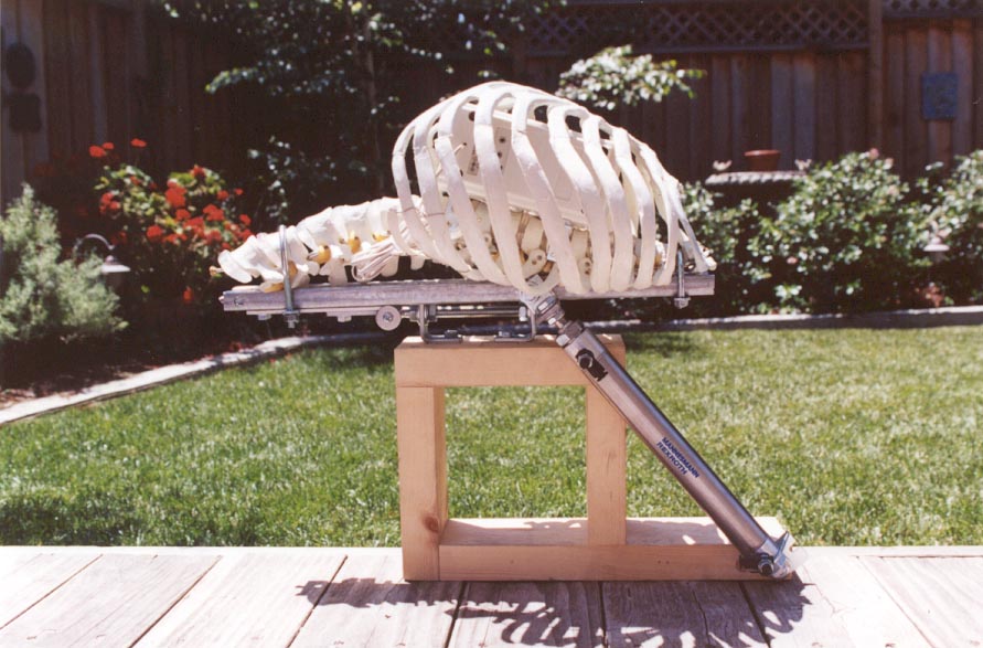
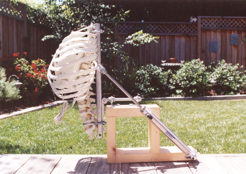
The corpse body is made from a Bucky ribcage (CH-10R4 - $27.00 each), Bucky's Right Arm and Hand (CH-46R/D, $9.50) and Bucky's Left Arm and Hand (CH-46L/D - Left, $9.50). Notice that Bucky's tailbone was removed, as where several vertebrae in his neck.
Bucky's spine rests in a 19 1/2" length of Unistrut. The rib cage is secured to the Unistrut using a pair of U-bolts. From these pictures, you can see the amplified speaker that is mounted in Bucky's ribcage.
The base is made from 2x4s, L1, L2, L3 and L4.
The corpse pivots using a bolt hook and a hinge strap. The hinge strap is bolted to the Unistrut. The bolt hook is secured to the base using a pair of angle brackets.
I drilled a hole in the end of the bolt hook. I tapped the hole to accept a machine screw. I used a machine screw and washer to keep the hinge strap from slipping off of the bolt hook.
The brackets are similar to those used to attach the 12" Pneumatic Cylinder to the lid.
The 8" Pneumatic Cylinder is secured to the base using a 3" long, 1/2" lag screw through the Foot Bracket. The 8" Pneumatic Cylinder is secured to the Unistrut using a 2 1/2" long, 1/4-20 bolt.
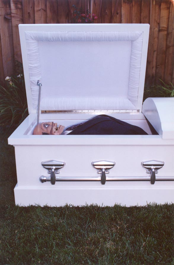
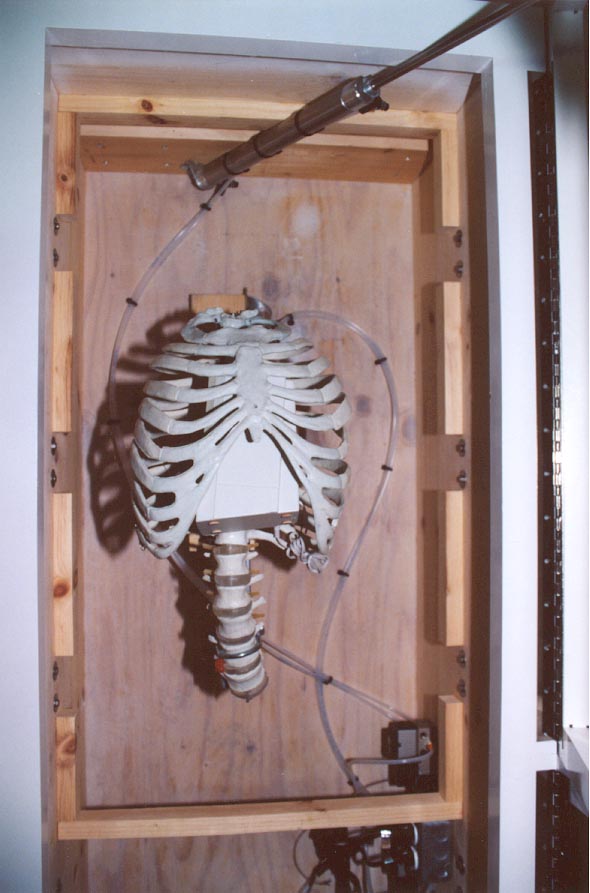
The corpse assembly is mounted to the floor of the coffin. The assembly is offset slightly towards the front of the coffin. This is to allow the corpse's head to clear the 12" Pneumatic Cylinder.
|
$2.18 x 7 = $15.26 |
|
Teflon Thread Seal Tape |
$1.19 |
|
1 /4" NPT Female Plug Air Quick-Disconnect Fitting |
|
|
1 /4" Brass Nipple |
|
|
1 /4" Brass Couple |
$1.79 |
|
1 /4" Compression Brass Tee |
$1.69 |
|
1 /4" Compression Inserts (3) |
$0.49 - 2 Inserts |
|
$0.07 per Foot |
Tools: Exact-o Knife, Wrenches, Drill
Miscellaneous: Cable Ties
Compressed air is connected to the Air Quick-Disconnect Fitting on the back of the coffin. The Quick-Disconnect Fitting is attached to a 1/4" Brass Nipple that passes through the wall of the coffin and the base board. On the inside of the coffin, the 1/4" Brass Nipple is attached to a 1/4" NPT x 1/4" Compression Fitting using a 1/4" Brass Couple. A short length of 1/4" Polyethylene Tubing connects the compression fitting to a 1/4" Compression Brass Tee. A short length of 1/4" Polyethylene Tubing connects the brass tee to a 1/4" NPT x 1/4" Compression Fitting at the inlet of each solenoid valve. Make sure to use 1/4" Compression Inserts when securing the 1/4" Polyethylene Tubing to the tee.
A very important aspect of the plumbing is the way in which the pneumatic cylinders are connected to the solenoid valves. I recommend plumbing the lid solenoid valve such that the lid is open when power is not applied. The corpse solenoid valve should be plumbed such that the corpse is at rest when power is not applied. This helps to ensure that if air pressure is applied without power to the solenoid valves (or if power is removed while air pressure is applied) that the lid will open and the corpse will return to a resting position.
Air pressure should always be applied to the coffin with the lid closed and the corpse at rest. If air pressure is applied while the lid is open, the lid may crash shut.
All four of the flow control valves will be almost completely closed. Start by opening each flow control valve a quarter turn.

The corpse head is constructed from a slightly modified version of Jamie Di Stefano's "How to Build A Corpse Easy Step by Step Instruction Manual" at Di Stefano Productions. Jamie sells the manual for $19.95 (plus shipping). It's well worth it. Out of respect for Jamie, I won't detail his entire technique here. I will, however, detail my modifications to his technique.
|
$16.99 |
Jamie recommends the use of the Lindberg Human Skull (71301, $16.99). I had originally planned on using an "old" Bucky skull (CS-20/4, $5.50), however, the weight of the skull is a concern when it comes to the servomotors. I could have used a "new" Bucky skull (CH-S2, $7.95) which is much lighter than the "old" Bucky skull and more inline with the Lindberg skull. The "new" Bucky skull is also much cheaper than the Lindberg skull. But I wanted to mount the jaw servomotor inside the skull. The Lingberg skull has a calvarium cut (i.e. removable skull cap). The "new" Bucky skull does not. I opted to go with the Lindberg skull.
|
|
|
|
16 Ounce Plastic Drinking Cups (2) |
|
Beech Nut Table Time Six Ounce Plastic Soup Can Lid |
|
Klean Klay |
Tools: Scissors
Miscellaneous: Five-Minute Epoxy, Dixie Cups, Craft Sticks
Jamie recommends making a lifecast of a human ear. The mold is made using dental alginate and the cast is made using Ultracal-30 plaster. Mask latex is applied to the Ultracal cast in order to make a latex ear "form".
I applied a similar technique only I cast the ears using Por-A-Kast with Watertrap. Por-A-Kast is a urethane casting compound which results in a reasonably hard, solid plastic ear which can be glued to the skull. Urethane normally doesn't like water and the dental alginate mold will be 50% water. Watertrap is a zeolite powder, which when combined with Por-A-Kast, allows it to be cast into a dental alginate mold.
 -
-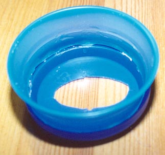
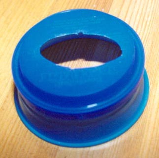
I made the form from a Beech Nut Table Time six ounce plastic soup can lid and a 16 ounce plastic drinking cup. I cut an oval shaped hole into the center of the soup can lid in order to accept my ear. The size of the hole should correspond to the base of your ear (where it meets your head). I cut off the bottom of a 16 ounce plastic drinking cup such that it fit into the soup can lid. I epoxied the cup into the lid.
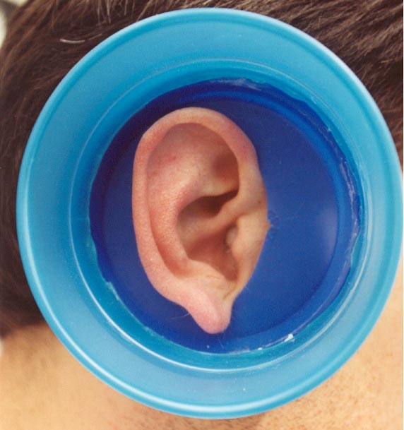
I slipped the assembly over my ear. Your ear should be centered within the form and there should be at least a 1/4" between the form and your ear.
You really need a helper for this part.
I combined four ounces of dental alginate with approximately five ounces of water. You don't want the resulting mixture to be too thick or it's hard to work in and around your ear.
Note
: Make sure that you put cotton in your ear before applying the dental alginate.You will want to lay on something comfortable and ensure that the lip of the cup is parallel to the floor.
Have your helper work the dental alginate in and around your ear. Have them try to eliminate the possibility of air bubbles as best they can. Air bubbles will show up as "warts" on the finished cast. Have them spoon the remainder of the dentail alginate into the form.
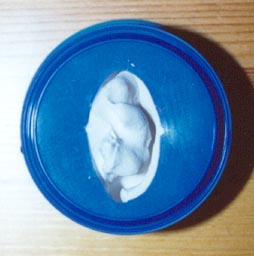
Allow the dental alginate to set-up (approximately 10 minutes) and then slowly and gently remove the plastic form (with the dental alginate) from your ear. Your ear is relatively flexible and you should be able to remove the mold from your ear without tearing it (the mold that is). I've made half a dozen ear lifecasts and have never had a problem.
 -
-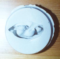
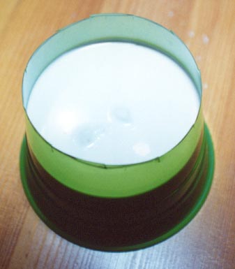
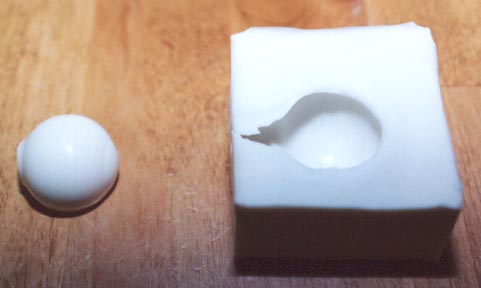
The picture on the left shows the form after it has been removed from my ear. The picture on the right shows the dental alginate mold after it has been removed from the form.
Place the mold into a second plastic drinking cup. The mold should be oriented the same way that it was with respect to the first plastic drinking cup. The mold should perfectly fit into the second cup.
Make a mark approximately 1/2" below the "top" of the mold (between the mold and the bottom of the cup). Remove the mold and cut off the bottom of the cup at the mark. Replace the mold into the cup. You will need to secure the mold to the cup such that it will remain in place when the cup is turned over on to its lip. I used a bead of Klean Klay. Now you should be able to turn the cup over. The bottom of the cup should be facing up and you should be able to see the opening of the mold.
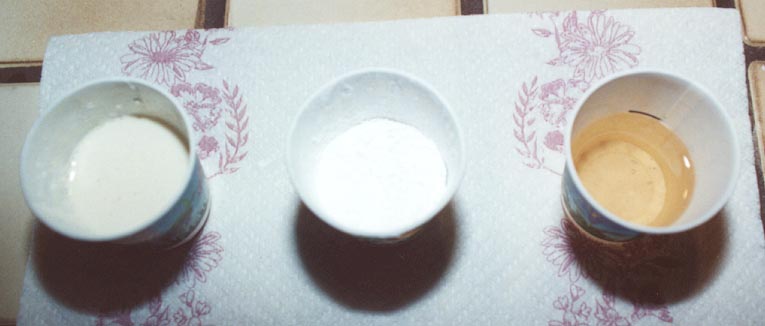
You can now prepare the Por-A-Kast. The Por-A-Kast is a two-part liquid consisting of a prepolymer and a curative which are to be combined one-to-one by volume. I measured equals parts of prepolymer and a curative into a pair of Dixie bathroom cups. I added an equal amount of Watertrap to the prepolymer and an equal amount of Watertrap to the curative.
In the picture above, the Watertrap has already been added to the prepolymer. The Dixie cup in the middle is waiting to be added to the curative in the Dixie cup on the right. The Watertrap should be combined with the prepolymer and curative separately and thoroughly.
I then combined the prepolymer and curative into a single Dixie cup, mixed thoroughly and poured the mixture into the dental alginate mold. The mixture should come up approximately 1/4" past the flat surface of the mold and almost level with the highest point of the "inner ear".
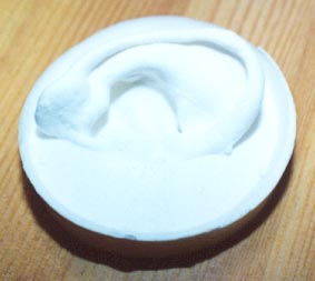
It will take approximately 10 minutes for the cast to setup. Again, slowly and gently remove the cast from the mold. The cast is not flexible and will (unfortunately) likely tear the mold. You can judge whether you want to make additional casts from the mold or not.
I used a Dremel to cut the round base away from the ear.
I opted to epoxy the ears to the skull before I began to apply latex.
|
|
Acrylic Teeth Set, http://www.monstermakers.com |
|
1 /8" Wood Dowel |
|
Five-Minute Epoxy |
|
GI 1000 Mold Making Silicone, http://www.monstermakers.com |
|
Foam Core |
|
Klean Klay |
|
Rubbing (Isopropyl) Alcohol |
|
Mold Release |
Tools: Exact-o Knife, Hot Glue Gun
Bucky's teeth are too perfect. Bucky must have been a male model. Jamie recommends removing teeth and chipping teeth, but you really can't get away from the fact that the teeth are straight, even and perfectly spaced. I opted to make my own teeth.
I started with a complete set of dentures from The Monster Makers. The Monster Maker's dentures are relatively expensive (a complete set of 28 teeth is $24.95) and I planned on making several corpse heads. Also, The Monster Maker's dentures don't have "roots".
The top, back-most four teeth (on the left and right) are identical to the bottom, back-most four teeth (on the left and right). For that matter, the left, back-most four teeth are almost identical to the right, back-most four teeth. I opted to only include the top, back-most four teeth (on the left and right) in the mold giving me a total of 20 teeth.
I made 1/4" - 3/8" long roots from a 1/8" wood dowel. I cut one end of the dowel at an angle using an Exact-o knife to match the curvature of the tooth. I secured a root to each tooth using a hot glue gun. I used a small amount of Klean Klay to fill-in around the root of the larger back teeth.
I pressed the teeth and roots into a 1" (wide) x 3/8" (thick) by 10 1/2" (long) block of Klean Klay. I pressed each of the front-most teeth into the block of clay until the "side seam" of each tooth was flush with the clay. I pressed the larger back teeth halfway into the clay. Each "root" should be depressed halfway into the clay and the end of each root should be flush with the edge of the clay. I spaced each tooth 1/2" on center.
I centered the block of Klean Klay on a 3" x 12 1/2" piece of foam core. I made a form from a 3/4" (high) by 23" (long) piece of foam core. I wrapped the foam core form around the block of clay. I used a bead of Klean Klay to seal the gap between the form and the foam core base.
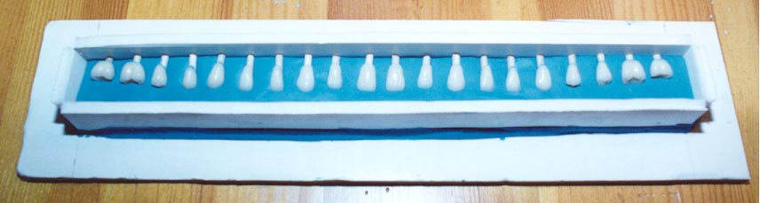
I poured GI 1000 silicone from The Monster Makers into the form and allowed the mold to dry overnight. I removed the form and carefully separated the clay from the silicone mold. Any clay residue should be removed from the surface of the mold using rubbing alcohol.
I centered the silicone mold on the foam core base and replaced the form. I applied a coat of mold release to the silicone mold. I poured GI 1000 silicone into the form and allowed the mold to dry overnight. I removed the form and carefully separated the two halves of the mold.
The teeth were cast using tooth shade acrylic from The Monster Makers. Tooth shade acrylic is a two-part powder (acrylic)/liquid (monomer).
I laid the two parts of the mold on a flat surface such that the holes corresponding to the roots of each tooth were next to one another.
I combined the acrylic and the monomer in a Dixie cup, approximately one-to-one by volume by eye. The acrylic and monomer need to be mixed thoroughly and very quickly, as the combination tends to setup fast. I formed a small spout by creasing the lip of the Dixie cup. I poured the dental acrylic into each tooth, quickly working from one half of the mold to the other. I filled as many teeth as I had dental alginate. I "folded" one half of the mold over onto the other and carefully aligned to the two halves of the mold. I placed a small board along the length of the mold and placed a small weight on the board. Again, the dental alginate sets up very quickly. You should be able to remove the cast teeth from the mold within 10 minutes.
I bought a 7" x 11" x 1 3/4" plastic box from a local hardware store. The plastic box has individual 1 3/4" x 1 3/4" compartments that I use to catalog the teeth. I used a different compartment for each type of tooth. I find that it's easier to catalog the teeth as they are removed from the mold as opposed to trying to figure out which tooth is which later.
Out of the mold, the teeth will have a natural color, but a dull finish. The natural, glossy finish comes from applying five-minute epoxy. With this project, I opted to apply the epoxy to the teeth before they were glued into the skull. In hindsight, I think that this was a mistake. You will likely need to grind the sides of the teeth a bit in order to make them fit. I think that it would be easier to apply the epoxy to the teeth after they are glued into the skull.
All of the Lindberg skull teeth are removable. I drilled an 1/8" hole into the jawbone corresponding to each tooth in order to accept the "root". You don't have to be (want to be) terribly precise here. Dry-fit the teeth before gluing them into place. You'll likely find that the teeth don't all fit. In order to alleviate this, you can grind down the sides of the teeth using a Dremel, you can turn a tooth or two cockeyed or you can always have one or two "missing" teeth. Once you have the teeth the way you want them, you can glue them in place and apply a coat of five-minute epoxy.
|
|
|
Tools: Dremel
Jamie recommends using cotton and latex to extend the bridge of the nose, possibly applied over a stiff piece of cardboard glued to the inside of the bridge. I opted to make a lifecast of my nose.
I simply globbed dental alginate on my nose and waited for it to setup. I cast Por-A-Kast with Watertrap into the mold. I cut the tip of the nose off with a Dremel. I ground out a cavity in the nose using a Dremel and drilled out the nostrils. I pulled apart a latex-soaked ball of cotton and inserted it in the cavity.
I glued the nose to the skull and "transitioned" the nose into the cheeks, lips and forehead using cotton and latex.
The cheeks and neck are made from sheets of latex. I applied latex to a mirror using a small foam roller.
Even with only two coats, the latex sheets tend to impede the movement of the jaw and neck. After several cycles, the cheeks began to tear. I simply left them that way. I repeatedly attempt to glue the latex which forms the neck to the 4" black ABS pipe cap, but the latex sheets tend to impede the movement of the jaw and neck. I opted to simply let the neck latex hang. The neck is mostly covered by the shirt collar anyway.
|
Full Round Acrylic Artificial Eyes (2), http://www.monstermakers.com |
$6.95 - Pair |
Tools: Dremel
I really like the effect of a corpse with eyeballs. I used eyeballs from The Monster Makers. I cut the stem from the eyeballs using a Dremel tool. I applied a thin layer of cotton and mask latex to the eye sockets and positioned the eyeballs within the eye sockets.
|
GI 1000 Mold Making Silicone, http://www.monstermakers.com |
|
Foam Core |
|
Klean Klay |
|
Tools: Exact-o Knife
I made a silicone mold of one of the eyeballs. This was a one-part mold. I pressed an eyeball approximately 1/4" into a 2" x 2" block of Klean Klay. The stem of the eyeball should be flush with the edge of the clay. I made a form from foam core. I poured GI 1000 silicone into the form.
I made the eyelids using a slush cast technique. I poured a small amount of Por-A-Kast into the mold and "rolled" the Por-A-Kast around the sides of the mold until it set-up (approximately 10 minutes). I cut the resulting cast into "wedges" which served as the eyelids.
I pressed the eyelids between the eyeball and the eye socket and applied a small, thin sheet of latex to transition the eyelid into the eye socket.
|
$54.95 - 4 Ounce 9 Color Kit (Red, Yellow, Blue, Black, White, Brown, Light, Medium and Dark Flesh) |
Tools: Airbrush
Arnold Goldman of The Monster Makers recommends the Paasche H airbrush set as part of his "The Monster Makers Mask Makers Handbook". I took Arnold's recommendation and purchased a Paasche airbrush from BearAir.
This was my first attempt at using the airbrush. Of course, I didn't take the time to watch the instructional video that came with the airbrush. I did skim through the instruction manual. I was pretty happy with the result, but I have a lot to learn.
|
|
$24.95 |
|
$11.95 |
|
$2.25 |
|
$4.99 |
|
$2.79 |
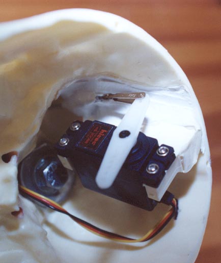
If there is interest, I will revise this website to discuss how the Servomotors were integrated with the corpse head.